Industry knowledge
Understanding Second Header Punch Tool Steel Selection
In cold heading, the Second header punch often dictates the final geometry and concentricity of a formed part. The tool steel grade selected must balance wear resistance against fracture toughness, particularly when forming shallow recesses or complex drive features. Common selections include M2 high-speed steel for general-purpose runs, while powder metallurgy grades like ASP 2023 or CPM M4 are preferred for high-volume production of stainless steel fasteners due to their isotropic microstructure. At Anzhikou Hardware, we often advise that micro-cracking at the punch tip is rarely a material defect but rather a symptom of misalignment in the die setup. As a manufacturer with 20 years of industrial production experience, we select tool steels based on the specific work hardening rate of your chosen wire, ensuring the Second header punch maintains its profile over millions of strokes.
Carbide vs. High-Speed Steel for Micro-Forming
When producing miniature screws with an external diameter of 0.6mm, the deflection characteristics of the Second header punch become the primary concern. Carbide punches offer superior compressive strength and minimal elastic deformation, which prevents "spreading" of the head diameter during impact. However, their lower tensile toughness makes them vulnerable to breakage if the wire feed length is inconsistent.
- Carbide (e.g., VF30): Best for extreme wear conditions at the cost of shock resistance.
- Powder Metal (e.g., PM30): Balances wear and toughness for complex head geometries.
- M2/Matrix II: Forgiving during setup; chips don't propagate as easily as carbide.
- Surface coatings like TiAlN are critical on HSS punches to prevent cold welding with stainless steel wire.
Suzhou Anzhikou's approach integrates tooling life analysis directly into our production planning, allowing us to promise product quality while preventing unexpected downtime caused by sudden punch failure.
Troubleshooting Eccentricity and Flash in Second Blow Operations
Dimensional drift in the Second header punch position creates specific forming defects that are often misdiagnosed. When the second punch axis doesn't perfectly align with the die bore, the resulting fillet thickness becomes asymmetric, causing eccentric head-to-shank runout. To isolate the punch as the root cause, check for flash concentration on one side of the head periphery. A uniform 360-degree flash ring typically indicates insufficient blank volume or low punch pressure, whereas sector-shaped flash points directly to punch alignment error or a worn punch guide bushing. We configure our precision equipment from Taiwan and Japan to maintain concentricity within micron tolerances, directly supporting our commitment to provide more professional service to customers needing high-precision fasteners.
The Influence of Quill Stroke on Punch Fill
The quill that houses the Second header punch must advance with exact timing relative to the material transfer. If the punch contacts the blank before it's fully seated in the die, the shank can bend, leaving a visible witness mark. A rapid-return mechanism is essential when heading shallow-drive recesses to avoid smearing the recess detail as the punch retracts.
- Verify blank transfer fingers release the wire completely before punch entry.
- Check for quill "bounce-back" using a dial indicator; excess clearance in the slide linkage amplifies punch instability.
- Monitor ejector sleeve timing — premature ejection causes the blank to tilt before the second blow completes.
Visual Defect vs. Likely Second Header Punch Cause
| Observed Defect |
Punch-Related Cause |
Immediate Check |
| Lopsided head rim |
Punch face out of square |
Re-grind face parallel to shank |
| Recess not centered |
Punch guide bushing wear |
Measure bushing clearance |
| Horizontal seam on head |
Punch retracting too slowly |
Adjust quill return spring tension |
Drawing on our 20 years of engineering expertise, Anzhikou Hardware incorporates these diagnostic steps into our non-standard screw customization process, helping you achieve stable mass production runs.
Balancing Clamp Force and Second Header Punch Penetration
The die clamping force applied during the second blow must be precisely calibrated against the penetration depth of the Second header punch. If the clamping sleeve grips the wire too tightly, the material cannot flow radially to fill the head cavity, resulting in under-fill at the flange corners. Conversely, insufficient clamping allows the wire to extrude backward along the shank, creating an uncontrolled increase in overall length. Our production methodology determines the optimal interference fit by analyzing the volume displacement curve specific to each head style. This precise control of force against punch travel is what allows us to confidently produce standard parts and non-standard screws up to an annual capacity of 2,000 tons, serving customers across 40 countries.
Die Ejector Pin Synchronization
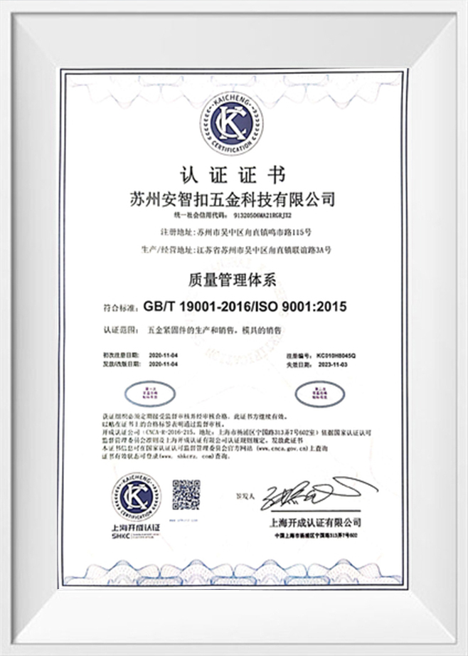
The ejector pin acts as a movable die bottom, and its back-pressure setting directly affects how the Second header punch fills intricate recess details. If the ejector yields too easily under the punch's force, the recess depth becomes inconsistent. We often set a dual-pressure relief sequence: a higher initial back-pressure for the main head forming, then a brief drop to allow stress relief without affecting the recess geometry. Having passed ISO9001:2015 quality system certification, we maintain strict documentation of these pressure profiles for every non-standard fastener order.
Preventive Maintenance Intervals Based on Wire Hardness
The hardness and coating of the raw wire dictate the resurfacing interval for a Second header punch. Forming phosphated steel wire is relatively benign, but processing uncoated stainless steel (304/316) introduces severe galling risks. A practical rule: for stainless wire above 250 HV, polish the punch nose every 200,000 strokes to remove microscopic adhered material before pitting develops. Operating with a punch that has lost its edge rounding introduces stress risers on the fastener head, which can lead to field failures. With 10 dedicated engineering and technical staff, Suzhou Anzhikou Hardware monitors tool wear curves relentlessly, and we promise the product quality by proactively scheduling tool changes before the wear limit is reached.
- Soft wire (≤200 HV): Inspect punch face for plastic deformation every 500k strokes.
- Stainless wire (200–280 HV): Polish nitride layer every 200k strokes; full re-coat at 1M strokes.
- High-strength alloy wire (>300 HV): Monitor for micro-chipping and increase punch hardness by 2 HRC if chipping occurs before 100k strokes.
Adhering to a "quality first, continuous innovation" philosophy, we see proactive punch maintenance not as a cost but as the defining factor that sustains tight dimensional tolerances over multi-million-piece orders.

 English
 Español
.jpg "Different Types Screw Header Punch Mould")
.jpg "Header punch second Punch for screw")
.jpg "High Quality M42 Second header punch with titanium coated")
.jpg "High Quality Screw Second Header Punch With TIN Coated")
.jpg "M2 M42 Durable Screw Second Header Punch Mold")
.jpg "TIN Coated Durable Screw Second Header Punch Mold")